We find machine and mechanism design without an inverse kinematic capability is difficult and time consuming. In fact, that is one of the main reasons we developed Mechdesigner.
What is Inverse Kinematics?
If we start by explaining forward kinematics. Suppose we have a mechanism - for example, a crank-slider, four-bar as shown in the sketch below. If we specify the position of the crank, we would use forward kinematic analysis to calculate the position of the slider. This is how most CAD systems work. You define a motion at the drive end of the mechanism and the CAD system calculates the position of all the parts in the mechanism according to that motion.
The problem with this approach is that as a designer, you are not particularly interested in the the motion of the motor shaft or the Cam-follower.
You want to design the motion of the tooling that is interacting with the product or pack. You need to make sure that velocities are matched, or that impacts are kept to a minimum. This is where inverse kinematics becomes important.
With inverse kinematic analysis, the motion of the tool or end-effector is designed. The inverse kinematic analysis will then calculate the position of the motor shaft or cam follower that is required to achieve that motion. A designer can now focus on the important aspects of machine design: designing the motion of the tooling. The inverse kinematic analysis will make sure that motor motion and cam profiles are correct.
This works even if a mechanism has two or three drives and the tool produces a planar or spatial path like a parallel robot. You design the path of the tool, MechDesigner works out what the drives need to do to achieve that path.
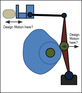
The Transfer Beam example, in the gallery image above, shows a classic example where inverse kinematic analysis can dramatically improve machine performance. The machine was required to take sets delicate products from a station and place then onto a continuously moving conveyor. The transfer beam needed to match the velocity of the conveyor during release to reduce impact velocity which would lead to damage or jams. Of course, even with this complicated two degree of freedom mechanism, the motions are defined at the tool. MechDesigner calculates all the necessary cam profiles to achieve the desired motion.
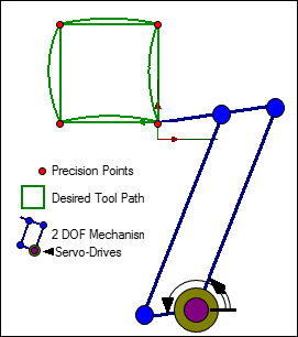
The image to the left, shows the Desired Path of the Tool - a square motion. In MechDesigner, you design this path with MotionDesigner. Any mechanism you design (with 2 Degrees of Freedom) will follow the path exactly (assuming parts are long enough).
MechDesigner, with its Inverse Kinematics capabilities, continuously derives the positions, velocities and accelerations for the Drive Axes. This information is very useful for Velocity and Acceleration Feed-forward Control Strategies.
However, if your software does not have inverse kinematics capabilities, then you will get a distorted path. At best, you will only be able to specify the positions of the servo drives at the 'precision' points.
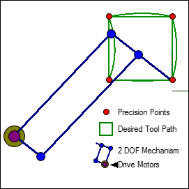
Also, the actual shape of the distorted path depends on the actual type of mechanism you use and also how it is configured.
For example, this mechanism is the same type, and it has the same part lengths.
However, the mechanism is connected in the machine frame at a different place. This is the only difference.
You can see the distorted path that will be followed by the tool is different to the distorted path followed by the mechanism in the image above.
And there are an infinite number of places you can position the mechanism, and an infinite number of part lengths.
MechDesigner will guarantee to follow the 'Desired Tool Path', whether you drive the mechanism with Servo Motors or Cams.